2
components. The air connection ports for SV-1
™
, SV-3
™
&
SV-4
™
valves are the same and are located in relatively the
same position on each model. All connections are pipe thread.
Lettering embossed in the valve body identifies two of the
four connection ports in these valves. Refer to the chart below
and figure one.
Air Connection Body Ident. Thread Size
Air Supply SUP 1/4" PT
Delivery DEL 1/4" PT
Control None 1/4" PT
Exhaust None 1/8" PT
IMPORTANT: An exhaust check valve should be installed in
the threaded exhaust port of these valves when they are
mounted outside the cab in unprotected environments.
SV-1
™
Synchro Valve
The SV-1
™
valve is a general purpose valve used in a variety
of applications on trucks, buses, tractors, trailers and
converter dollies. The SV-1
™
valve is the base valve from
which both the SV-3
™
and SV-4
™
valves are derived. It is
offered in a variety of pressure settings to accommodate
applications where automatic operation is required. It is easily
distinguished from the SV-3
™
and SV-4
™
valve by its smaller
size.
SV-3
™
Trailer Release Valve
While originally designed for automatic operation to
accomplish brake release on trailers without spring brakes,
the SV-3
™
valve can be used in any installation where its
single automatic pressure setting is advantageous. The
SV-3
™
valve is very similar in appearance to the SV-4
™
valve
but can be distinguished by measuring the length and
diameter of the supply hex cap nut (1/4" PT supply port).
See the comparison chart for the dimensions.
SV-4
™
Trailer Release Valve
The SV-4
™
valve was designed primarily for use on trailer
converter dollies to minimize the possibility of false charging.
Like the SV-3
™
valve it can be used in other applications.
The SV-4
™
valve is the combination of two valves; an SV-3
™
valve and a single check valve. A typical installation is
illustrated in figure 4. The SV-4
™
valve can be distinguished
from the SV-3
™
valve using the dimensions given in the
comparison chart. In addition, the tip of the check valve
contained in the SV-4
™
valve is visible at the bottom of the
¼" PT supply port.
SV-3
™
/SV-4
™
Valve Comparison
Supply Cap Nut Dimensions
Diameter Length
SV-3 .8125" 1.162"
SV-4 .94" 1.062"
OPERATION
GENERAL
The SV-1
™
, SV-3
™
, & SV-4
™
valves all operate in a similar
fashion. All can be connected in the air system so that other
valves control them. When connected in this non-automatic
mode the valve serves as a remote mounted, On-Off control.
They can also be installed so that they function automatically
or self actuate at a preset pressure. Automatic operation is
the most common application. Regardless of how they are
connected the internal valve operation is the same.
NON-AUTOMATIC (valve controlled remotely by another
valve)
With no air pressure present at the control port, supply port
air pressure and the inlet/exhaust valve spring hold the inlet
valve on its seat in the body. The piston is held away from
the inlet/exhaust valve by the piston spring, and the delivery
line is vented to atmosphere through the hollow exhaust
stem of the piston.
When sufficient air pressure is applied to the control port,
the control piston moves against the resistance of its return
spring. As the control piston moves, it contacts the exhaust
valve portion of the inlet and exhaust valve which seals the
hollow exhaust passage in the piston stem. Continued piston
movement drives the inlet valve from its seat and allows
supply air to flow through the body and out the delivery port.
When air pressure is removed from the control port, the
piston return spring and delivery port air pressure move the
piston away from the inlet/exhaust valve. As the piston moves,
the inlet valve re-seats itself preventing air flow to the delivery
port. Continued movement unseats the hollow exhaust
passage in the piston stem allowing delivery air to flow
through the stem and out the exhaust check valve.
FIGURE 4 - TRAILER CONVERTER DOLLY
SV-1
™
SYNCHRO
SINGLE CHECK VALVE
Note: An SV-4
™
valve can be used in place of the
SV-1
™
valve and single check valve shown here.
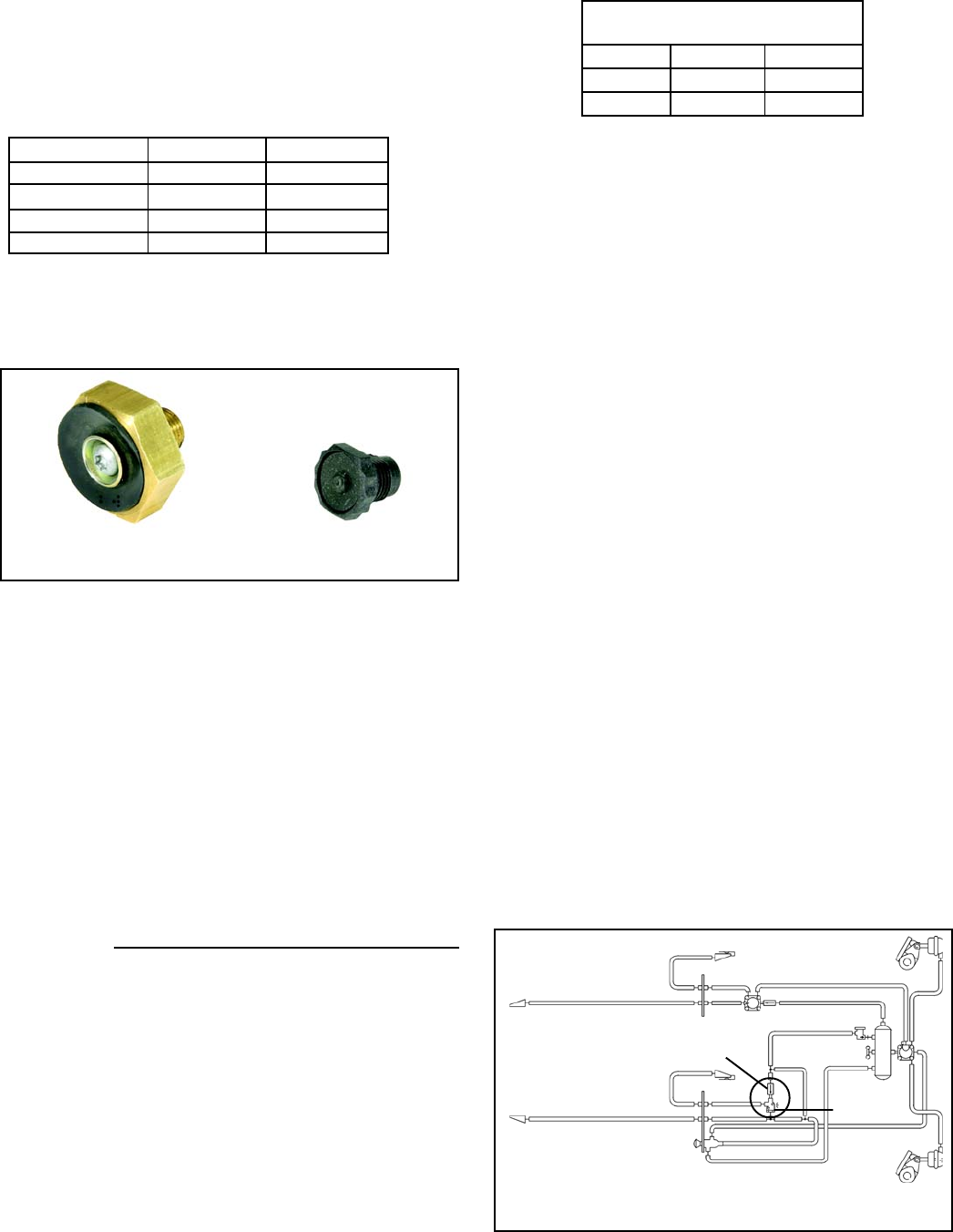
FIGURE 3 - EXHAUST CHECK VALVE STYLES
1/8" PIPE THREAD
1/8" PIPE THREAD
Note: Either style may be installed in the
SV-1
™
, SV-3
™
or SV-4
™
valves
 (6 strony)


 (2 strony)
 (1 strony)
 (2 strony)
 Manymanuals.com
 Manymanuals.de
 Manymanuals.fr
 Manymanuals.it
 Manymanuals.pl
 Manymanuals.cz
 Manymanuals.es
 Manymanuals-pt.com
Komentarze do niniejszej Instrukcji